


The Jabsco technical team at Xylem explain the advantages and characteristics of flexible impeller pumps for cooling and the different types of marine engine cooling systems that they work with
There are several things to consider regarding marine engine cooling systems, including which types of pumps and systems are most appropriate for your application. Here we will review:
- The advantages of flexible impeller pumps (FIPs).
- The cooling systems that are most used for marine propulsion engines.
- Safety margins.
- Guidance on suction systems.
- Pump types and what to consider.
- The different pump drives that are available.
IMPORTANT: The data in this article relating to engine cooling systems and pump selection is for guidance only. It does not cover high-performance engines. You should always consult the engine manufacturer or mariniser.
Jabsco engine cooling pumps and systems must be matched during the design of the boat’s engine installations. Once installed, safety margins must be safeguarded, and the emphasis must be on preventive, not corrective maintenance.
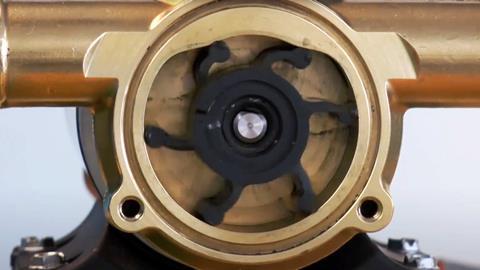
The advantages of flexible impeller pumps
Flexible impeller pumps are versatile. They combine the priming feature of positive displacement type pumps with the general transfer ability of centrifugal pumps. Flexible impeller pumps will pump thin or viscous liquids and can handle more solids in suspension than rotary pumps. They operate at low or high speeds, can be mounted at any angle, and pump in either direction equally efficiently. Additionally, flexible impeller pumps are:
- Self-priming. FIPs pump instantly with dry suction and lift up to 10ft (3m) or up to 25ft (8m) when wetted, permitting cleaner, safer installations. No foot valve is required.
- Simple. FIPs have one moving part—a tough, long-lived, wear-resistant flexible impeller lubricated by the pumped liquid. No metal-to-metal pumping action means no gears jam, clog or become noisy.
- Capable of handling more capacity. FIPs generally require less space because they deliver greater flow for weight, size and price than other types of pumps.
Pressure ranges
Standard impellers are suitable for continuous operation up to the following limits:
- 1/4in, 3/8in and 1/2in port sizes to 40ft (12m) head, 17.3 psi (1.2 bar)
- 1in to 2in port sizes to 70ft (20m) head, 30.3 psi (2 bar)
Special high-pressure impellers are available for certain models. Operating in the lower portion of the recommended pressure range will extend the life of the impeller.
Temperature range
The temperature range is 45°F to 180°F (7°C to 80°C). For fluids less than 45°F (7°C), please consult with Xylem.
Operating speeds
Below are the operating speeds for ball bearing pumps by size:
- 1/4in or 1/2in ports: 3600 rpm maximum
- 3/4in or 1in ports: 3000 rpm maximum
- 1-1/4in ports: 2200 rpm maximum
- 2in ports: 2200 rpm maximum
Marine propulsion engine cooling system types
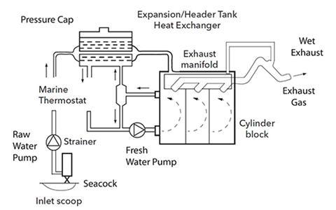
Heat exchanger cooling
This is also known as a closed system because the primary cooling circuit is isolated from the surrounding atmosphere.
A centrifugal pump circulates fresh, treated water through the cylinder block passages and around the tube stack of a heat exchanger. The Jabsco raw water pump draws raw water (from sea or lake) through the ship’s hull inlet and pumps it through the heat exchanger tubes, removing the heat transmitted from the primary circuit before discharging it overboard.
The heat exchanger, which can be single-pass or two-pass type, should handle approximately 10 per cent more than the maximum engine heat rejection rate and may be fitted separately or as an integral part of the expansion/header tank. This tank allows the venting of air or combustion gasses absorbed by the cooling water during engine operation and provides a positive pressure on the freshwater pump inlet. This pump, fitted in the coldest part of the primary circuit, has a capacity to maintain a water temperature differential of approximately 45°F (8°C) across the cylinder block at full load.
Most engines have a marine thermostat that regulates the engine operating temperature to about 185°F (85°C). To provide an adequate safety margin for commercial diesel engines, which may be expected to operate more than 2500-3000 hours per year, the size and rpm of the Jabsco raw water pump should be selected to give a flow capacity of approximately 15gpm (57lpm) for every 100hp maximum engine load and rpm.
The raw water pump flow capacity should be 10-15 per cent higher if an exhaust manifold is fitted in the raw water or freshwater circuit.
Additional coolers, such as oil coolers or charge air coolers, must be fitted after the pump, but in a compromise between reliability, size and weight, and pump delivery. The head should be around 10-13 psi of water at maximum rpm.
Safety margins in pump inlet systems are extremely critical, so any restrictions or bends, other than seacock and inlet strainers, are to be avoided at all costs.
Raw water from the exhaust manifold is often injected into the exhaust pipe (after an exhaust elbow to prevent raw water flowback into the cylinders), which may then be ducted through areas where a hot pipe would create a hazard. This is known as a “wet exhaust” system. In addition, mixing of water with exhaust gases will reduce exhaust noise. However, on small engines the raw water flow should not be less than 2.5- 4 GPM (9.5-15 LPM) for adequate silencing.
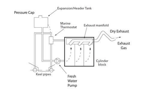
Keel cooling
This is like a heat exchanger-cooled system, but the raw water circuit and heat exchanger have been replaced by pipes attached externally to the vessel’s keel.
Pipe bore and surface area must be adequate for effective heat dissipation from the primary circuit to sea or river water. In some installations, where the centrifugal circulating pump’s flow capacity is insufficient due to system pressure losses through keel pipes, cylinder block, and exhaust manifold, a Jabsco pump may be used – flow capacity approximately 30gpm (113lpm) for every 100hp at maximum engine load and rpm.
Alternatively, a steel hull may be used as the cooling surface, where the heat is transmitted directly to the surrounding sea or river water from a tank welded inside to the bottom.
The dry exhaust can be made a wet exhaust by a separate raw water pump.
The expansion/header tank may be fitted separately. In this case, it must be connected directly to the circulating pump inlet, and the primary circuit adequately vented into the tank.
Direct cooling
Raw water is pumped directly through the engine block. However, as the water entering the block is at ambient temperature, the outlet temperature needs to be much lower than in an indirect cooled engine to reduce the formation of scale and salt deposits and thermal stresses in the cylinder block.
Lower operating temperature means that engine performance will be considerably less efficient, and direct cooling systems should not be used on commercial craft engines.
For weekend pleasure craft engines which operate no more than 50-100 hours per year, reliability margins will probably be maintained for several years until deposits in the engine cooling passages begin to affect heat transfer to the cooling water.
Engine operating temperature is best controlled by a marine thermostat rather than a manually operated valve.
For cold engine start, the thermostat will be closed, and most of the cooling water (about 10gpm (38lpm) for every 100hp at full load and speed) will bypass the engine via a spring-loaded back pressure valve and discharge into the exhaust manifold. A small bleed hole in the thermostat will ensure a slow circulation of cooling water through the cylinder block to prevent hot spots while the engine is warming.
Safety margins
The raw water flow capacities indicated earlier are for diesel engine cooling systems and include a safety margin of some 30 per cent to ensure adequate engine cooling under adverse operating conditions.
Gasoline engines (compared to diesel engines), have a high heat rejection rate at idling speed, so an increase in pump flow capacity of some 10 per cent at maximum rpm is recommended.
While flow capacities can be affected by salt deposits or scale in pipes due to operation in tropical regions, seawater pollution, age, and wear of pumps and systems in general, this is usually a gradual process with ample warning that preventive maintenance can counteract.
Far more severe is a reduction in cooling water flow due to adverse conditions caused by an inadequate system.
When marine vegetation, such as seaweed, gets stuck in seawater inlet strainers with insufficient mesh or hole size, the cooling water supply to the pump can be significantly reduced.
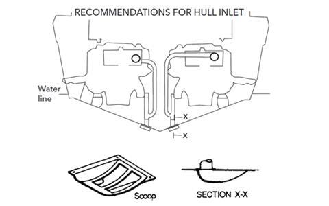
On the other hand, no amount of pump flow capacity will safeguard against a sudden but total blockage—for example, a plastic bag covering the hull inlet. The system safety margin can be substantially increased by providing two separate hull inlets, usually on either side of the keel, joining the pump inlet pipe below the water line. In actual practice, the likelihood of both inlets being covered simultaneously is insignificant.
As heat exchanger and cooler manufacturers’ recommendations for a given engine performance and corresponding pump flow will include appropriate safety margins for minimum and maximum flow, it should be kept in mind that excessive water velocities through the heat exchanger pipes due to ’overkill,’ such as fitting oversize cooling pumps, may cause pipe erosion and accelerated pump wear through excessive pump operating pressures.
On the other hand, low water velocities through heat exchanger tubes could result in sludge formation. Therefore, a pump that is too small (insufficient safety margins) may cause inefficient operation of heat exchangers and coolers for a long time.
Suction system
A raw water-cooling pump must operate in a correctly designed cooling system to provide reliable performance under seagoing conditions. Therefore, it is essential that cooling water reaches the pump without having to overcome undesirable resistance or restrictions.
The following general rules are given for guidance:
The bore of the suction pipe must not be smaller than the pump inlet connection, but if the total length of the suction pipe exceeds 10ft (3m), the bore should be one size larger, particularly if the pump is operated at high speeds. Avoid sudden enlargements or contractions in pipe bore and use the same size throughout. If a change in bore size is needed use long tapered sections to achieve that.
- The suction pipe run should be as straight as possible and avoid unnecessary bends. Do not use square or standard elbows, instead use long sweep bends.
- Do not fit gearbox or engine oil coolers in the pump suction system. Always install after the pump.
- Seacocks of the same nominal size as the suction pipe work should be of the ball or plug type, giving complete through bore in the open position. The handle position should indicate whether the seacocks are open or closed.
- Seawater inlet strainers should have a hole or mesh size of at least 1/8in (3mm) diameter and up to 3/16in (5mm) for larger pumps, but smaller than the heat exchanger tube bore.
- Check frequently that the inlet filter is not clogged. If in doubt, clean thoroughly.
- Fast boats (over 12-15 knots) must be fitted with inlet scoops in a permanently wetted area of the ship’s hull to create sufficient inlet pressure at higher boat speeds. Flush inlet fittings are not suitable for fast boats.
Pump selection
Most proprietary marine engines already have specially adapted flange-mounted Jabsco cooling pumps driven by gears or couplings of various descriptions.
A belt drive from the crankshaft pulley will enable almost any standard foot-mounted bronze Jabsco pump to be selected, provided that the required cooling flow rate is obtained without the pump being operated at excessive speeds.
Global cooling water requirement for each 100hp at maximum engine load and rpm is as follows:
Diesel engines
Heat exchanger cooling – 18gpm (68lpm) — raw water
Keel cooling 36gpm (136lpm) — fresh water
Direct cooling 12gpm (45lpm) — raw water
Gasoline engines
Use the numbers from the diesel engine chart above and increase by about 10 per cent.
If exhaust manifolds are water cooled, increase the pump capacity by a further 10-15 per cent.
Pump types
Selection may depend upon pump speed, space available and type of drive.
Ball bearing pumps
Ball-bearing pumps should be used for pump speeds in excess of 2500 rpm. Depending on size and duty, speeds of up to 5000 rpm are possible, but special attention to suction system conditions is required (consult Jabsco).
Ball-bearing pumps are available in heavy-duty and compact types.
Heavy-duty pumps
This range is designed with two spaced bearings and mechanical rotary face seals to meet high-reliability criteria under adverse operating conditions, such as excessive belt tension, high operating pressure, abrasive conditions found in shallow waters or in-shore operation. Pump bodies are either bolted to a bearing housing or the body and bearing housing are a single, integral casting. These pumps are often unique to the application, but some varying pump types can share common bearing housings.
Compact pumps
This pump range is fitted with double-row ball bearings, providing a low-cost compromise between overall pump length and limited heavy-duty capability.
Bearings are shielded, ensuring permanent lubrication by the special grease.
Pump drive failure
Badly designed pump systems cause most pump failures. Unsatisfactory drive arrangements are secondary causes of pump problems.
Pump drives
Direct drives
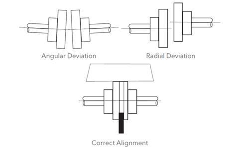
Misalignment between the pump and the drive shaft is a common cause of pump failure.
A flexible coupling is only “flexible” within the limitations specified by the manufacturer. Excessive misalignment, particularly at high pump speeds, can cause noise, knocking, vibration, and premature bearing failure, which is usually followed by pump leakage.
Belt drives
The pump speed is determined by the engine pulley diameter and the need to maintain the pump pulley at a practical maximum size. Some engine crankshaft pulleys incorporate vibration dampening membranes, resulting in large diameters at the v-groove. To lower pump speed relative to engine speed, it is necessary to use a pulley on the pump that is larger than the drive pulley. High engine speeds may, therefore, require oversized pump pulleys, which preclude the practicality of a belt drive. Calculating a suitable size pump pulley requires you to:
- Divide the drive pulley diameter by the pump pulley diameter
- Multiply the result by the engine speed to obtain the pump speed
Excessive drive belt tension will cause rapid belt wear and may result in premature bearing failure. Applying finger pressure should be able to deflect a correctly tensioned belt between pulleys approximately 1/2in–3/4in (13–19mm).
While excessive belt tension may be due to inadvertent overtightening, it should always be verified that it did not result from an inherent fault in the installation, e.g., if pump flow is inadequate due to a slipping belt caused by insufficient contact area between belt and pulley, any amount of tightening would not solve the problem permanently. The contact area should ideally be about 120° but not less than 90°.
If the engine is installed on flexible mountings, a belt-driven pump must be mounted on the engine, never bolted to the vessel’s structure. This is to avoid tensioning or slackening the drive belt due to the relative movements of the engine.
Gear drives
Drive gears fitted to heavy-duty flange-mounted pumps are supported by the pump ball bearings and driven by one of the engine gears.
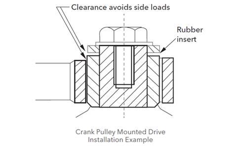
Crank Pulley Mounted Drive
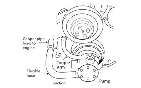
Several Jabsco pumps specially developed for high-speed operation on gasoline and diesel engines are fitted with a multi-positional bearing housing bolted directly to the crankshaft pulley, thus eliminating mounting brackets, belts and pulleys.
As the pump body is supported by the ball bearing only, it must be prevented from rotating by means of a torque arm designed and installed to avoid any side load on the bearing. Inlet and outlet hoses must be flexible and of adequate length (at least 10 times the hose diameter) so that the pump can be rotated freely over a few degrees by finger pressure only.
Reproduced with thanks from the Xylem white paper: Flexible Impeller Pumps Used in Marine Engine Cooling Applications


 LinkedIn
 X / Twitter
 Facebook
 Email us